What Are the Top 3 Drawbacks of Exceeding a Power Supply’s Input Voltage?
What Are the Top 3 Drawbacks of Exceeding a Power Supply’s Input Voltage?
What are the top three drawbacks that occur when operating a power supply outside of its specified limits?
A common question engineers have when designing power supply specifications is, “What if I operate my power supply outside of a certain specification range?” To help answer this question, the designer must outline the potential drawbacks and failures that could occur when operating a power supply outside of its specified limits. Let’s discuss the top three potential issues that can arise when the input voltage moves beyond a power supply’s allowable range.
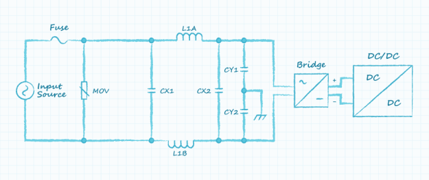 Typical ac-dc input (Photo: CUI)
Throughout the world, the available mains voltage and its associated stability can vary greatly, making it challenging to design a power supply that meets the input range needs of all applications. Assuming a power supply’s input specification is “close enough” to an application’s desired operating voltage can lead to failures if the power supply is operated outside of its limits. These failures can be defined as either component failures, system failures, or specification failures, and each will impact power supply and system performance differently.
Component failures occur when a component is damaged and no longer operates as intended. Applying a voltage that exceeds a component’s maximum operating voltage is a simple way to damage any component. Many components that are placed across the input, such as the X-capacitors, metal oxide varistors (MOV), and bridge rectifiers are easy to identify as being subject to voltage stress. If the input voltage exceeds their maximum operating voltage, the specific failure mode of these components can lead to a few different scenarios. For example, X-capacitors, which are designed to fail short for safety reasons, will likely open the fuse leaving the power supply inoperable. However, if Y-capacitors, which are designed to fail open, were to fail short, the power supply may continue to operate, leaving users at risk of shock.
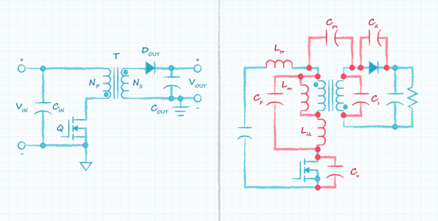 Left: typical flyback schematic with discrete components Right: flyback schematic with parasitic components added in red (Photo: CUI)
Other components, such as the fuse, are more difficult to identify as being susceptible to failure in the event of an overvoltage. Under normal conditions, the fuse will appear as a short, and an increase in voltage will simply force the fuse to carry less current. If a failure, such as an X-capacitor short, occurs inside the power supply, the fuse will open and disconnect the circuit from the input source. However, if the maximum voltage of the fuse is exceeded and the X-capacitor shorts, the fuse will not be able to suppress arcing. This will fail to keep the circuit open leading to continued current flow through the failed capacitor, causing problems both up and downstream.
Recommended For You: Powerful Breakthrough Batteries, Cheap and Easy to Make
In other instances, the voltage stress is related to parasitic components whose values are difficult to determine. The switch in a flyback converter, for example, has a peak voltage determined not only by the input voltage but also the leakage inductance and turns ratio. In cases such as this, the voltage stress cannot always be determined by simply looking at the schematic or datasheets. The voltage stress, instead, must be measured directly.
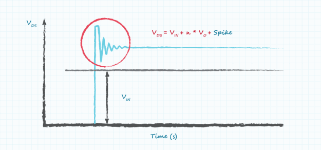 Flyback switch voltage contributions (Photo: CUI)
Under voltage events also have the potential to cause component failures. When operating a power supply below the minimum operating voltage, the current in many components will increase proportionally. The fuse, rectifier, switches, and other components that carry this increased current will all dissipate more power, leading to increased temperature and chance of failure. Magnetic components, such as a power factor correction (PFC) choke, will also carry more current and as a result, see their inductance drop or saturate entirely. Depending on the specific topology, this could lead to increased peak current (potentially damaging components like the switch), increased operating frequency, decreased efficiency, or failed power conversion all together.
When parameters such as operating frequency or duty cycle range are violated, system failures can result in causing the internal functions of various topologies to misbehave. For example, an LLC converter varies the operating frequency to regulate the output voltage, with the frequency being inversely proportional to the input-to-output gain of the converter. However, if the input voltage decreases, then the frequency will also decrease in order to increase the gain and maintain a constant output voltage. An inherent characteristic of the LLC converter is that the gain curve only maintains this inverse relationship of frequency-to-gain down to a certain frequency. Below this frequency, the relationship becomes reversed (i.e., gain increases with frequency). If the input voltage decreases to the point where the power supply drifts into this region (known as the capacitive region), the power supply can malfunction or fail completely.
Some non-isolated converters, including the boost converter used in a PFC circuit, only converts in one direction, up or down. In the case of a boost converter, it only outputs a voltage higher than the input voltage. If an ac-dc power supply with power factor correction is operated with an input voltage greater than the output of the boost converter voltage, the boost converter will not work and fail to correct the power factor. Similarly, a buck converter, which converts from high input to a low output, cannot operate at a voltage lower than the output voltage. The buck converter also contains a switch whose gate is not referenced to ground, and as a result, uses a bootstrap circuit to produce the gate-source voltage to drive the FET. This bootstrap circuit relies on the switching action to create the gate voltage, so, when the input voltage is too close to the output voltage, the switch timing prevents the bootstrap circuit from producing the gate drive voltage, and the circuit ceases to work.
You May Also Like: How Gallium Nitride Enables Smaller, More Efficient Power Supplies
Power supplies also carry built-in protection circuits to prevent operation under certain conditions. This becomes more common at higher power levels as failures are more dangerous and expensive. Brown-out protection is a feature commonly found in higher power ac-dc power supplies, which shuts down the supply if the input voltage drops below a specified threshold.
Operating outside of the specification does not always cause a complete failure, but instead causes the power supply’s performance to fall outside of its specification. As stated previously, decreasing the input voltage will cause an increase in input current, which leads to increased losses and heat, while reducing the operating temperature range and efficiency.
To protect the power supply from catastrophic failure, the controllers often have protection built in to avoid certain conditions. These protections will not shut down the power supply but will instead clamp a characteristic at a certain value. For example, in the case of the LLC topology, there are often frequency limits inside the controller. As described earlier, as the input voltage decreases, the switching frequency will increase to maintain a constant output voltage. If the controller clamps the frequency once it reaches the minimum, then the output voltage will begin to decrease along with the input voltage.
Further Reading: How to Destroy Lithium-Ion Batteries?
While the impact on specification performance is easy to estimate in certain instances such as those described above, the effects of input voltage in other instances are harder to predict. One such example is the relationship between the input voltage and electromagnetic emissions (EMI). Operating outside of the specified input voltage range can have a big impact on EMI and lead to non-compliance with relevant regulations. The added voltage or current stress can further change the effectiveness of the EMI filter, and for variable frequency, devices change the operating point to a level that causes failure.
Input voltage impacts many aspects of a power supply, including the component stresses, operating point, and performance. Operating outside of the specified range can affect one or more of these items and, if pushed too far, trigger a protection circuit or total failure. Knowing how far a power supply can be pushed in a certain direction and what the implications would require knowledge of the internal component ratings and values, which are rarely available to the user and are difficult to determine. The best way to determine the safe operation of a power supply outside its specified input voltage range is to ask the manufacturer, who can identify the risks and implement the design changes needed to allow operation at the desired level.
Input Voltage Limits
Typical ac-dc input (Photo: CUI)
Throughout the world, the available mains voltage and its associated stability can vary greatly, making it challenging to design a power supply that meets the input range needs of all applications. Assuming a power supply’s input specification is “close enough” to an application’s desired operating voltage can lead to failures if the power supply is operated outside of its limits. These failures can be defined as either component failures, system failures, or specification failures, and each will impact power supply and system performance differently.
1. Exceeding Input Voltage Limits—Component Failures
Component failures occur when a component is damaged and no longer operates as intended. Applying a voltage that exceeds a component’s maximum operating voltage is a simple way to damage any component. Many components that are placed across the input, such as the X-capacitors, metal oxide varistors (MOV), and bridge rectifiers are easy to identify as being subject to voltage stress. If the input voltage exceeds their maximum operating voltage, the specific failure mode of these components can lead to a few different scenarios. For example, X-capacitors, which are designed to fail short for safety reasons, will likely open the fuse leaving the power supply inoperable. However, if Y-capacitors, which are designed to fail open, were to fail short, the power supply may continue to operate, leaving users at risk of shock.
Left: typical flyback schematic with discrete components Right: flyback schematic with parasitic components added in red (Photo: CUI)
Other components, such as the fuse, are more difficult to identify as being susceptible to failure in the event of an overvoltage. Under normal conditions, the fuse will appear as a short, and an increase in voltage will simply force the fuse to carry less current. If a failure, such as an X-capacitor short, occurs inside the power supply, the fuse will open and disconnect the circuit from the input source. However, if the maximum voltage of the fuse is exceeded and the X-capacitor shorts, the fuse will not be able to suppress arcing. This will fail to keep the circuit open leading to continued current flow through the failed capacitor, causing problems both up and downstream.
Recommended For You: Powerful Breakthrough Batteries, Cheap and Easy to Make
In other instances, the voltage stress is related to parasitic components whose values are difficult to determine. The switch in a flyback converter, for example, has a peak voltage determined not only by the input voltage but also the leakage inductance and turns ratio. In cases such as this, the voltage stress cannot always be determined by simply looking at the schematic or datasheets. The voltage stress, instead, must be measured directly.
Flyback switch voltage contributions (Photo: CUI)
Under voltage events also have the potential to cause component failures. When operating a power supply below the minimum operating voltage, the current in many components will increase proportionally. The fuse, rectifier, switches, and other components that carry this increased current will all dissipate more power, leading to increased temperature and chance of failure. Magnetic components, such as a power factor correction (PFC) choke, will also carry more current and as a result, see their inductance drop or saturate entirely. Depending on the specific topology, this could lead to increased peak current (potentially damaging components like the switch), increased operating frequency, decreased efficiency, or failed power conversion all together.
2. Exceeding Input Voltage Limits—System Failures
When parameters such as operating frequency or duty cycle range are violated, system failures can result in causing the internal functions of various topologies to misbehave. For example, an LLC converter varies the operating frequency to regulate the output voltage, with the frequency being inversely proportional to the input-to-output gain of the converter. However, if the input voltage decreases, then the frequency will also decrease in order to increase the gain and maintain a constant output voltage. An inherent characteristic of the LLC converter is that the gain curve only maintains this inverse relationship of frequency-to-gain down to a certain frequency. Below this frequency, the relationship becomes reversed (i.e., gain increases with frequency). If the input voltage decreases to the point where the power supply drifts into this region (known as the capacitive region), the power supply can malfunction or fail completely.
Some non-isolated converters, including the boost converter used in a PFC circuit, only converts in one direction, up or down. In the case of a boost converter, it only outputs a voltage higher than the input voltage. If an ac-dc power supply with power factor correction is operated with an input voltage greater than the output of the boost converter voltage, the boost converter will not work and fail to correct the power factor. Similarly, a buck converter, which converts from high input to a low output, cannot operate at a voltage lower than the output voltage. The buck converter also contains a switch whose gate is not referenced to ground, and as a result, uses a bootstrap circuit to produce the gate-source voltage to drive the FET. This bootstrap circuit relies on the switching action to create the gate voltage, so, when the input voltage is too close to the output voltage, the switch timing prevents the bootstrap circuit from producing the gate drive voltage, and the circuit ceases to work.
You May Also Like: How Gallium Nitride Enables Smaller, More Efficient Power Supplies
Power supplies also carry built-in protection circuits to prevent operation under certain conditions. This becomes more common at higher power levels as failures are more dangerous and expensive. Brown-out protection is a feature commonly found in higher power ac-dc power supplies, which shuts down the supply if the input voltage drops below a specified threshold.
3. Exceeding Input Voltage Limits—Specification Failures
Operating outside of the specification does not always cause a complete failure, but instead causes the power supply’s performance to fall outside of its specification. As stated previously, decreasing the input voltage will cause an increase in input current, which leads to increased losses and heat, while reducing the operating temperature range and efficiency.
To protect the power supply from catastrophic failure, the controllers often have protection built in to avoid certain conditions. These protections will not shut down the power supply but will instead clamp a characteristic at a certain value. For example, in the case of the LLC topology, there are often frequency limits inside the controller. As described earlier, as the input voltage decreases, the switching frequency will increase to maintain a constant output voltage. If the controller clamps the frequency once it reaches the minimum, then the output voltage will begin to decrease along with the input voltage.
Further Reading: How to Destroy Lithium-Ion Batteries?
While the impact on specification performance is easy to estimate in certain instances such as those described above, the effects of input voltage in other instances are harder to predict. One such example is the relationship between the input voltage and electromagnetic emissions (EMI). Operating outside of the specified input voltage range can have a big impact on EMI and lead to non-compliance with relevant regulations. The added voltage or current stress can further change the effectiveness of the EMI filter, and for variable frequency, devices change the operating point to a level that causes failure.
Be Sure to Ask The Manufacturer
Input voltage impacts many aspects of a power supply, including the component stresses, operating point, and performance. Operating outside of the specified range can affect one or more of these items and, if pushed too far, trigger a protection circuit or total failure. Knowing how far a power supply can be pushed in a certain direction and what the implications would require knowledge of the internal component ratings and values, which are rarely available to the user and are difficult to determine. The best way to determine the safe operation of a power supply outside its specified input voltage range is to ask the manufacturer, who can identify the risks and implement the design changes needed to allow operation at the desired level.
What are the top three drawbacks that occur when operating a power supply outside of its specified limits?
Sponsored by
Related Content
Jul 30, 2026
Ion Beams Speed Qualification for Nuclear Materials

By mimicking years of neutron damage in days, ion beam testing could dramatically reduce the time and cost of qualifying materials for advanced nuclear reactors.

Jun 18, 2026
Superconductors Reimagined

Reimagined superconductors could deliver zero-resistance power under real-world conditions. The solution lies in the substrate.

May 12, 2026
The End of Brittle Solar

Flexible carbon nanotubes replace brittle ITO in perovskite solar cells, boosting durability, efficiency, and lowering costs for next generation renewables.

Feb 19, 2026
Surface Roughness Accelerates Hydrogen Embrittlement

A team at Chiba University has identified the causal relationship between the roughness of pipe surfaces and the development of hydrogen embrittlement.