7 Tools for the Metrology Engineer's Toolbox
7 Tools for the Metrology Engineer's Toolbox
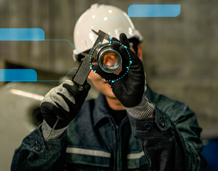
Metrology engineers use a variety of tools,to measure tolerances and processes.
It is important for manufacturers to keep pace with product trends, especially the need for tight tolerances at increasingly smaller scales, which requires higher-precision equipment. For example, micro features can be as small as a few thousandths of an inch with positional tolerances of one thousandth of an inch.
Metrology is evolving rapidly, largely through data acquisition speed and software capabilities, to keep up with smaller and more complex devices. Continual growth in computing power and programming has made many advances in inspection technology possible. Because speed is increasingly urgent for manufacturers, especially with supply chain delays, product inspection needs to be fast, accurate, and nondestructive.
Here are seven tools that metrology engineers utilize to measure product dimensions and manufacturing processes.
Coordinate-measuring machines (CMMs)
This equipment features a high-precision probe that physically touches the surface of a part to collect critical-dimension data and analyze that information to see if the product complies with the original CAD dimensions. Although CMMs are highly accurate, they do require parts be physically removed from the production line to be measured off-line, which slows down production.More for You: Seven Ways IoT Super-Charges Lean Manufacturing
Laser scanners
Typically hand-held or mounted on robot arms, laser scanners project a laser dot or a laser line onto a product surface that captures data in real-time. Millions of reference points can be collected within a few seconds, without touching the surface, making laser scanners an ideal tool for measuring delicate products or complex geometries.
Blue-light 3D scanner
Using the principles of triangulation, these scanners project a fringe pattern of light across a part’s surface. As the patterns change during each scan, cameras record the distortion at different angles to determine 3D coordinate measurements. The resulting 3D images detail complex geometric features of the part and any surface defects. Scans can capture up to 100 frames per second with high precision.
CT scanning
X-ray computed tomography (CT) equipment can inspect parts inside and out, providing the unique ability to detect internal flaws that cannot be seen using a surface scan. It is also a rapid process; scan times of a few tenths of seconds per part are possible. CT scans can achieve accuracy to the millionth inch (.000001 inches), whereas most traditional CMMs are accurate to the nearest ten thousandth inch (.0001 inches).
Adaptive machining
Adaptive or “hybrid” machining equipment integrates measurement technology with machining tools on the same machine. Using laser sensors, measurements for a component can be collected in real time as the component. This in-line ability to determine dimensions assures top quality by determining any variances in real time and making adjustments as needed.
Reader’s Choice: 5G Pilot to Test Factory of the Future Concept
Optical photogrammetry system
Optical photogrammetry is a measurement system for larger objects, such as sheet metal parts, car bodies, and aerospace components. Reference points are placed on the target object and technicians walk around the object, using a portable hand-held digital photogrammetry system that performs fast and accurate 3D coordinate measurements. Although CMMs can also perform these measurements, it is a more cumbersome process and takes longer to complete.
Digital twins
High-resolution 3D-scanning technologies, such as laser scanners or CT scanners, can be used to collect millions of geometric data points for a part that are then used to easily create an exact digital replica, or digital twin, of that part, including the finest micro features and flaws that cannot be seen with the naked eye. Variables for the digital twin can then be manipulated to test adjustments to the manufacturing process that will eliminate those defects and/or improve operational efficiency.
Advances in modern metrology tools and technologies continue to improve the quality of manufactured parts and streamline manufacturing operations, resulting in better product quality, faster production speed, and shorter time to market. The ease of making digital twins using hand-held 3D scanners gives engineers an easy way to create product/process models and simulations that are essential to continuous process improvement and expanding engineering strategies and design possibilities.
Mark Crawford is a science and technology writer in Corrales, N.M.
Metrology engineers use a variety of tools,to measure tolerances and processes.

Writer and editor at MC2 Solutions
Related Content


