Applying Newton's Laws to Pipe Forces Caused by Fluid Transients is Tricky
Applying Newton's Laws to Pipe Forces Caused by Fluid Transients is Tricky
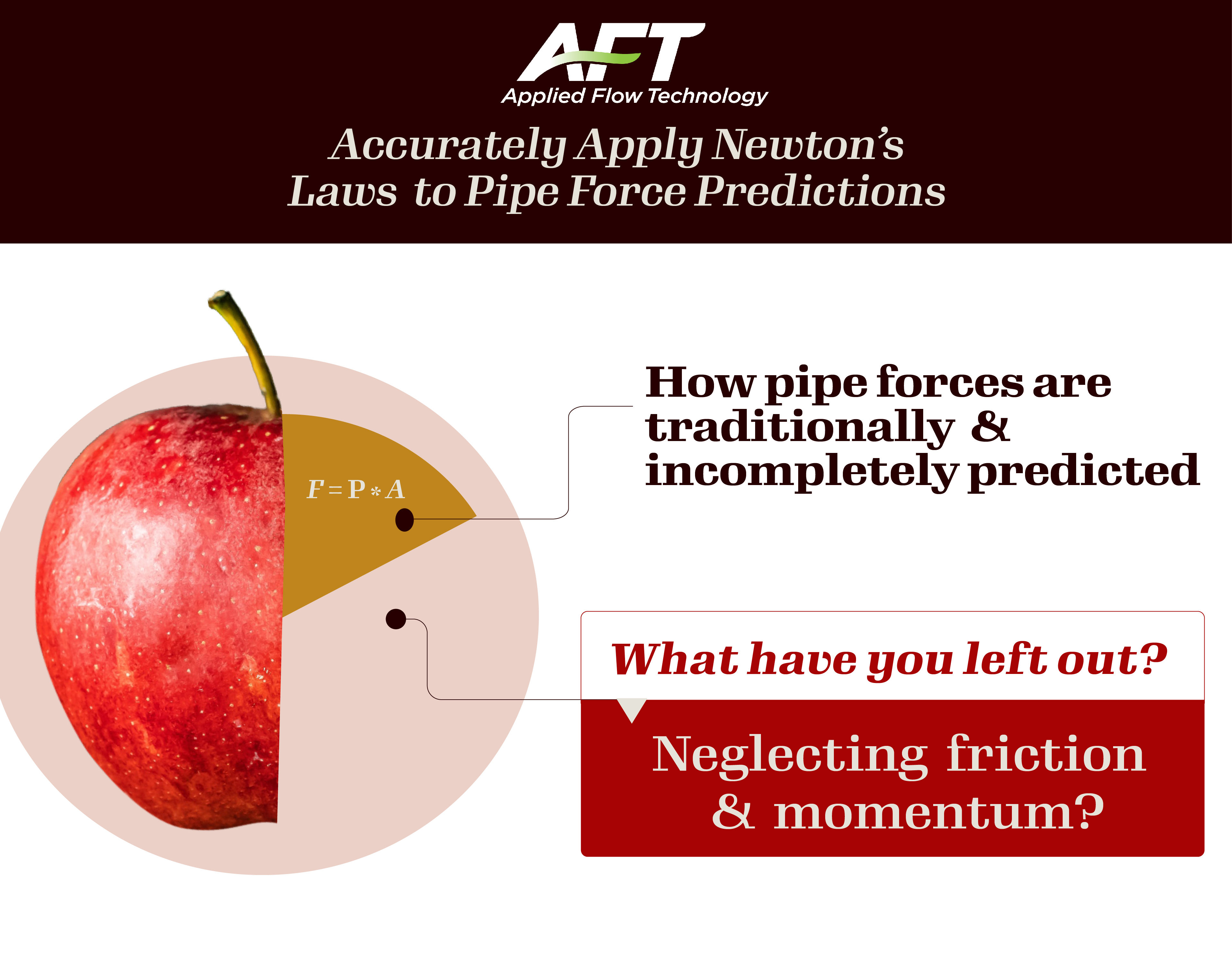
How to accurately apply Newton by including friction forces and momentum changes.
Surge transients are often called waterhammer in liquid systems and steam hammer in steam systems. The high (acoustic) velocity pressure waves in these applications can cause short duration but high amplitude forces – especially in configurations such as pipe runs between elbow pairs. Forces in excess of 10,000 lbf (50 kN) are common.
Fig. 1 depicts a wave propagation at acoustic speed, a, and resulting forces.
a. At the top of Fig. 1 the transient has not started, the pipe run 1-2 is in equilibrium, and no net force exists.
b. In the center, the wave is initiated at the right from a valve (not shown) which is closed instantly. The wave travels at acoustic velocity, a. When it reaches the pipe run 1-2, a net force exists that pushes the pipe elbow assembly to the right. This force must be supported by external pipe supports or the pipe elbow assembly will bend and literally move to the right.
c. At the bottom the wave has passed the pipe run 1-2 and the entire elbow assembly. While now at a much higher pressure than at the top, pipe run 1-2 is again in equilibrium and no net force exists any longer. Note that if the wave reflects from a boundary point on the left, it will travel back through the elbow assembly and exert another net force.
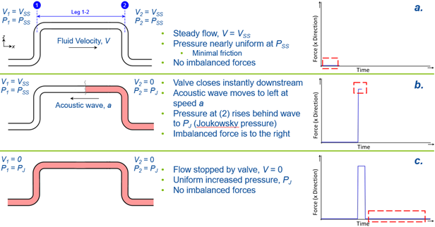 Figure 1: Wave propagation at acoustic speed; a. and resulting forces.
At first glance this would not seem to be an overly complicated task. But the underlying reality is much more complex than most engineers realize. Newton’s Second Law of Motion can be employed to assess the maximum forces. However, one first needs a reasonably accurate transient fluid dynamic solution available in order to plug in the pressures and velocities into Newton.
Due to the resulting complexity, engineers have often used a simplified approach they believe to be conservative. Frequently this involves using the Joukowsky Equation or something similar to determine a maximum pressure differential. This pressure differential is then used to estimate a force as shown below. This simplified approach can be called the Endpoint Pressure Method.
Endpoint Pressure Method (simplified approach, from Fig 1b)

Since we know the values of P1 and P2 in Fig 1b, we can write Eq. 1:

While perhaps appropriate for an earlier generation of engineers who designed piping using slide rules, calculators, or even spreadsheets, this simplified approach is fraught with potential error and often badly misestimates the forces. It can even be unconservative and give design loads much too low. And in the incorrect direction!
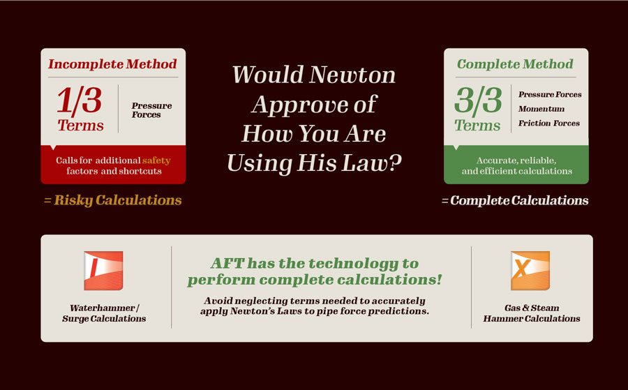
Waterhammer software such as AFT ImpulseTM can be used by engineers to determine transient pressures and velocities for liquid systems. However, engineers often take the resulting software output and attempt to use Newton by only considering pressure forces (e.g., they still use Eq. 1). This approach might seem to be appropriate, but in fact it mistakenly disregards certain parameters in Newton such as forces due to friction and momentum changes in the liquid. While it is true these disregarded parameters are often minimal and can be safely neglected, there are many cases where they are important and cannot be neglected. AFT Impulse performs a complete force balance using all parameters in Newton and is thus able to give a more accurate force prediction. More on this below.

Gas and steam transients often do not generate sufficiently high transient forces to merit detailed simulation. However, there are some applications which do. One such application is steam hammer in large diameter power station piping. Simulating such behavior is significantly more complicated than for liquids. AFT xStreamTM is designed to handle such challenging applications and, from what we can tell, it is the only commercially available software that can do this for transient steam flow. Moreover, and similar to AFT Impulse, AFT xStream is designed to account for all parameters in Newton’s Second Law.
So, what is wrong with Eq. 1?
Two papers recently published at the 2022 ASME PVP conference get into all the details. Here we will summarize. The complete force balance can be determined as follows:
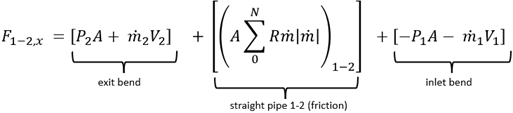
Component Reaction Method (complete method)
Equation 3
where the pipe force from frictional resistance is given by summing the friction in each computing section, 0 to N, as follows:
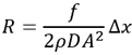
Eq. 3 is called the Component Reaction Method. Comparing Eq. 3 to Eq. 1, it is clear that Eq. 1 is a special case of Eq. 3. . First, the fluid momentum, ṁV, can and does change from point 1 to 2 because of the waterhammer wave. Second, there is friction in the pipe. If each of these terms is negligible, then Eq. 1 is a reasonable approximation to the force. Often these terms are negligible. However, there are cases when they are not. The ASME papers explain this.
Further, Eq. 3 is not that difficult to use for liquid surge transients. But for steam transients (or gases in general) it is more complicated to determine the needed parameters. Fortunately, if one draws a different control volume around pipe run 1-2 in Fig. 1, it can be shown that an equivalent way of calculating the force is given by:
Acceleration Reaction Method (complete method)
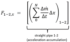
Equation 4
Eq. 4 sums up the change in acceleration for each computing section, 0 to N. It is therefore called the Acceleration Reaction Method. It is valid for liquids and gases. It can be shown that it is complete and yields the same force predictions as Eq. 3. And when a computational solution is available through a simulation model, it is straightforward to use.
The ASME papers discuss more complicated pipe arrangements than shown in Fig. 1, and how to apply Eqs. 3 and 4 to these situations.
Eqs. 1, 3 and 4 are cross-plotted vs. AFT Impulse results in Fig. 2. Here you can see that the simplified approach in the Eq. 1 Endpoint Pressure Method obtains inaccurate and unconservative force predictions.
AFT recommends the use of the Eq. 4 Acceleration Reaction Method for general use by all engineers. It includes all terms in Newton’s Second Law and will not lead engineers astray. The Eq. 3 Component Reaction Method is also complete and safe to use but can be more difficult to calculate in practice.
Thanks to the advancement of technology, it’s not a stretch to complete these calculations efficiently – YOU CAN HAVE THE TIME if you use AFT Impulse and AFT xStream to make this an easy task.
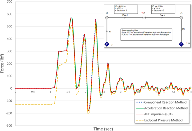
Figure 2. Force predictions for the system shown at upper right using Eqs. 1, 3 and 4. AFT Impulse results are cross plotted. The Impulse results lay on top of the Component Reaction Method and Acceleration Reaction Method.
Scott Lang, PE, is a senior engineering software developer at AFT in Colorado Springs, CO. He supports AFT by researching and developing numerical methods for modeling a variety of fluid systems. Of particular interest to him is the prediction of turbomachine behavior under steady, transient, or performance-impacting conditions, and the general analysis of transient fluid flow. He holds a Bachelor of Science in Engineering with Mechanical and Electrical specialties from the Colorado School of Mines and is a member of the Engineering Honor Society Tau Beta Pi.
Trey Walters, PE, is president and founder of Applied Flow Technology. His company develops simulation software for steady and transient fluid flow. He has performed and managed numerous consulting projects on fluid transients. He previously worked in the aerospace and power industries. He holds a BSME and MSME. He sits on several standards committees of the Hydraulic Institute and is chairman of their Waterhammer Committee. He is a Fellow of ASME.
To learn more about applying Newton’s Laws to predicting forces in piping systems, and to see how AFT’s transient simulation tools make calculating complete and accurate transient forces practically effortless, register for this webinar that will be conducted on Wednesday, Oct. 19, at 2 pm ET.
How to accurately apply Newton by including friction forces and momentum changes.
Sponsored by

Related Content
.jpg?width=854&height=480&ext=.jpg)


