How to Switch Mode Power Supplies Work, Block by Block
How to Switch Mode Power Supplies Work, Block by Block
Here is a power supply topology, for an understanding of major circuits internal to power suppliers.
Although you specify and use power supplies in your projects, they may be a ‘black box’ with unknown internals. While there is no need for you to be a power supply design expert, there are benefits to understanding the basic blocks internal to power supplies. In this article we will present a power supply topology and discuss each of the internal functional blocks to provide a fundamental understanding regarding the major circuits internal to power supplies.
Inside of Power Supplies
The block diagram in figure 1 is representative of many ac-dc or dc-dc power supplies. The difference in the block diagram between ac-dc versus dc-dc input supplies is the diode bridge rectifier. A rectifier circuit (diodes D1, D2, D3, D4) is required in ac-dc power supplies and is not needed for dc-dc power supplies, otherwise the power supply topologies can be identical.
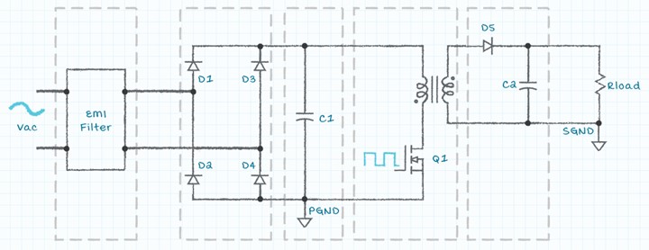 Figure 1: Simplified block diagram of ac-dc switching power supply
EMI/EMC Filter
The EMI/EMC filter block can be either components placed internal to the power supply by the power supply designer or added as external components by the user of the power supply. The EMI/EMC components may be required to serve the following functions:
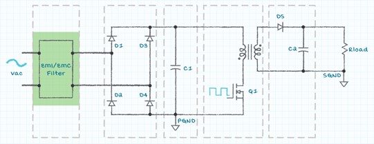 Figure 2: EMI/EMC input filter
Diode Bridge Rectifier
As mentioned previously, the diode bridge rectifier is used to convert the ac input voltage to a dc voltage for use within the power supply. The rectifier circuit is not present in a supply designed for only a dc input voltage since the dc voltage is already present. However, many power supplies designed for an ac input voltage have also been characterized to be powered by a dc input voltage. If a dc voltage is applied with a diode bridge present on the input of the supply, the dc voltage can be connected in either polarity and will pass through the diodes and appear on the input bulk capacitor.
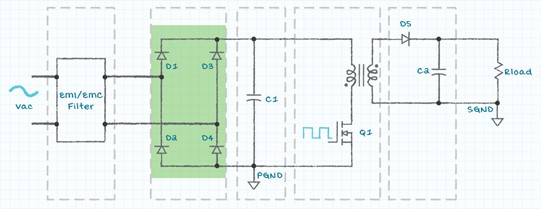 Figure 3: Diode bridge rectifier
Input Bulk Capacitor
The input bulk capacitor filters the dc voltage from the rectifier diodes in ac-dc power supplies and acts as an input filter in dc-dc power supplies. When the input voltage is first applied to a power supply the voltage across the input bulk capacitor will be 0 V. This difference in voltage between the applied voltage and the bulk capacitor voltage can cause a large input surge current while the bulk capacitor is charging up to the input voltage. This inrush current can be an issue as it may be 100’s of times greater than the normal input operating current. Often an inrush current limiter, which may be a simple as a small value resistor, is placed in series with the input voltage terminal to limit the inrush current.
On a dc-dc supply, the input bulk capacitor can help to compensate for the impedance of the input conductors and to stabilize the dynamic input impedance of the power supply. This web page https://www.cui.com/blog/negative-resistance-and-why-your-dc-dc-converter-may-not-working-properly provides more details regarding the input impedance of a power supply and how it may cause a supply to oscillate.
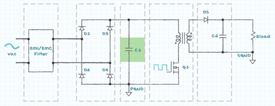 Figure 4: Input bulk capacitor
Input Power Switch
The electronic switch (drawn as a MOSFET) converts the dc input voltage to an ac voltage so that power can be passed through the isolation magnetics (transformer or coupled inductors). The duty cycle of the input control signal, and thus the output signal from the power switch, is dependent upon the topology of the supply, the input voltage, the output voltage, and the output load current. In ac-dc supplies, the reason for converting the ac input voltage to dc and then back to ac is because the internal ac frequency is much higher (tens of kilohertz to tens of megahertz) and thus smaller isolation magnetics and output filter components can be selected. In addition, the internal ac waveform may be modulated as part of the power conversion topology.
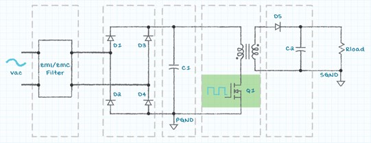 Figure 5: Input power switch
Isolation Magnetics
The common element used for the isolation magnetics is either a transformer or coupled inductors. With either a transformer or coupled inductors, there are one or more windings on both the primary and secondary side of the isolation barrier. In the physical construction of the isolation magnetics, there will be parasitic capacitance between the primary and secondary windings. This parasitic capacitance can be a source of EMI/EMC issues which need to be addressed and will be discussed in a separate web article. The diagram in Figure 6 represents the parasitic capacitance associated with the windings. It should be noted that in practice the capacitance is not a lumped element as shown in the diagram, but rather is distributed across and between the windings.
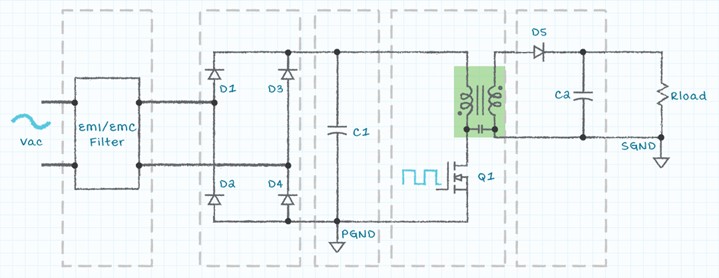 Figure 6: Isolation magnetics with lumped capacitor representing the parasitic capacitance.
Output Rectifier
The output voltage of the isolation magnetics is an ac waveform and needs to be rectified to produce a dc output voltage. Either a passive circuit (diodes) or an active circuit (FETs) can be used to perform the rectification. The rectification circuit can be half-wave, full-wave, or other configurations, depending upon the output voltage requirements and isolation magnetics construction. Diode rectifiers are low cost and simple to construct, but the power dissipation will be greater than if an active FET rectifier circuit were implemented.
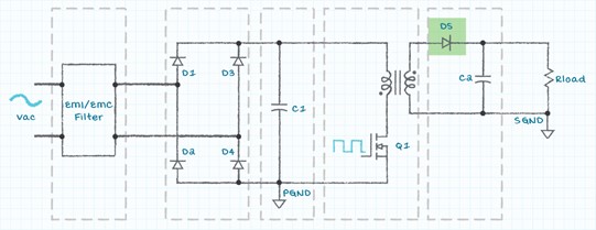 Figure 7: Output rectifier
Output Filter
The output rectifier will produce a dc voltage with an ac voltage superimposed on it. Without output filtering, the peak-to-peak magnitude of the ac noise will be equal to the dc voltage and will be unacceptable for most applications. The basic output filter is one or more capacitors placed across the output voltage. Output filtering can be enhanced by the addition of a series inductor to create either an ‘L’ filter or a ‘Pi’ filter. The output filter is sometimes implemented to suppress EMI/EMC emissions. Output filters are most effective when the components are placed close to the power supply load. Placing the filter components close to the load minimizes the voltage drop on the conductors caused by variations in the load current.
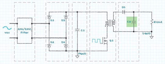 Figure 8: Output filter capacitor
Voltage, Current and Temperature Control
Circuits to regulate the output voltage, output current and power supply maximum temperature are also included in both ac-dc and dc-dc power supplies. These control circuits have complex sets of characteristics and are discussed in a separate web article.
This discussion has covered the internal functions found in ac-dc and dc-dc power supplies at a high level. In other articles we discuss functions included to regulate the output of the power supply, methods used to protect the power supply and load from damaging operation, components required to meet EMI and EMC regulatory requirements, and effects of modifications to power supply specifications. Please contact the CUI sales and customer support teams for more information regarding the topics covered in this discussion if you have questions regarding how they apply to the power supply selected for your project.
Bruce Rose is principal application engineer for CUI.
Inside of Power Supplies
The block diagram in figure 1 is representative of many ac-dc or dc-dc power supplies. The difference in the block diagram between ac-dc versus dc-dc input supplies is the diode bridge rectifier. A rectifier circuit (diodes D1, D2, D3, D4) is required in ac-dc power supplies and is not needed for dc-dc power supplies, otherwise the power supply topologies can be identical.
Figure 1: Simplified block diagram of ac-dc switching power supply
EMI/EMC Filter
The EMI/EMC filter block can be either components placed internal to the power supply by the power supply designer or added as external components by the user of the power supply. The EMI/EMC components may be required to serve the following functions:
- Minimize radiated and conducted noise on the input of the power supply
- Minimize the effects of voltage transients applied from the input voltage source
- Minimize the input surge current when voltage is first applied to the input of the power supply
- Protect the input power source and conductors if there is a failure of the power supply
Figure 2: EMI/EMC input filter
Diode Bridge Rectifier
As mentioned previously, the diode bridge rectifier is used to convert the ac input voltage to a dc voltage for use within the power supply. The rectifier circuit is not present in a supply designed for only a dc input voltage since the dc voltage is already present. However, many power supplies designed for an ac input voltage have also been characterized to be powered by a dc input voltage. If a dc voltage is applied with a diode bridge present on the input of the supply, the dc voltage can be connected in either polarity and will pass through the diodes and appear on the input bulk capacitor.
Figure 3: Diode bridge rectifier
Input Bulk Capacitor
The input bulk capacitor filters the dc voltage from the rectifier diodes in ac-dc power supplies and acts as an input filter in dc-dc power supplies. When the input voltage is first applied to a power supply the voltage across the input bulk capacitor will be 0 V. This difference in voltage between the applied voltage and the bulk capacitor voltage can cause a large input surge current while the bulk capacitor is charging up to the input voltage. This inrush current can be an issue as it may be 100’s of times greater than the normal input operating current. Often an inrush current limiter, which may be a simple as a small value resistor, is placed in series with the input voltage terminal to limit the inrush current.
On a dc-dc supply, the input bulk capacitor can help to compensate for the impedance of the input conductors and to stabilize the dynamic input impedance of the power supply. This web page https://www.cui.com/blog/negative-resistance-and-why-your-dc-dc-converter-may-not-working-properly provides more details regarding the input impedance of a power supply and how it may cause a supply to oscillate.
Figure 4: Input bulk capacitor
Input Power Switch
The electronic switch (drawn as a MOSFET) converts the dc input voltage to an ac voltage so that power can be passed through the isolation magnetics (transformer or coupled inductors). The duty cycle of the input control signal, and thus the output signal from the power switch, is dependent upon the topology of the supply, the input voltage, the output voltage, and the output load current. In ac-dc supplies, the reason for converting the ac input voltage to dc and then back to ac is because the internal ac frequency is much higher (tens of kilohertz to tens of megahertz) and thus smaller isolation magnetics and output filter components can be selected. In addition, the internal ac waveform may be modulated as part of the power conversion topology.
Figure 5: Input power switch
Isolation Magnetics
The common element used for the isolation magnetics is either a transformer or coupled inductors. With either a transformer or coupled inductors, there are one or more windings on both the primary and secondary side of the isolation barrier. In the physical construction of the isolation magnetics, there will be parasitic capacitance between the primary and secondary windings. This parasitic capacitance can be a source of EMI/EMC issues which need to be addressed and will be discussed in a separate web article. The diagram in Figure 6 represents the parasitic capacitance associated with the windings. It should be noted that in practice the capacitance is not a lumped element as shown in the diagram, but rather is distributed across and between the windings.
Figure 6: Isolation magnetics with lumped capacitor representing the parasitic capacitance.
Output Rectifier
The output voltage of the isolation magnetics is an ac waveform and needs to be rectified to produce a dc output voltage. Either a passive circuit (diodes) or an active circuit (FETs) can be used to perform the rectification. The rectification circuit can be half-wave, full-wave, or other configurations, depending upon the output voltage requirements and isolation magnetics construction. Diode rectifiers are low cost and simple to construct, but the power dissipation will be greater than if an active FET rectifier circuit were implemented.
Figure 7: Output rectifier
Output Filter
The output rectifier will produce a dc voltage with an ac voltage superimposed on it. Without output filtering, the peak-to-peak magnitude of the ac noise will be equal to the dc voltage and will be unacceptable for most applications. The basic output filter is one or more capacitors placed across the output voltage. Output filtering can be enhanced by the addition of a series inductor to create either an ‘L’ filter or a ‘Pi’ filter. The output filter is sometimes implemented to suppress EMI/EMC emissions. Output filters are most effective when the components are placed close to the power supply load. Placing the filter components close to the load minimizes the voltage drop on the conductors caused by variations in the load current.
Figure 8: Output filter capacitor
Voltage, Current and Temperature Control
Circuits to regulate the output voltage, output current and power supply maximum temperature are also included in both ac-dc and dc-dc power supplies. These control circuits have complex sets of characteristics and are discussed in a separate web article.
This discussion has covered the internal functions found in ac-dc and dc-dc power supplies at a high level. In other articles we discuss functions included to regulate the output of the power supply, methods used to protect the power supply and load from damaging operation, components required to meet EMI and EMC regulatory requirements, and effects of modifications to power supply specifications. Please contact the CUI sales and customer support teams for more information regarding the topics covered in this discussion if you have questions regarding how they apply to the power supply selected for your project.
Bruce Rose is principal application engineer for CUI.
Here is a power supply topology, for an understanding of major circuits internal to power suppliers.
Sponsored by
Related Content

Jun 25, 2026
A Mighty Wind Project

You probably don’t know how much you fart. And turns out, nobody else does either. Researchers at the University of Maryland have created a tool to finally answer this vital question.

Jun 22, 2026
Blaze-Battling Bots Ahead

A novel system that uses AI-powered robots to extinguish fires could eliminate the need to put firefighters in dangerous situations.

Jun 18, 2026
Superconductors Reimagined

Reimagined superconductors could deliver zero-resistance power under real-world conditions. The solution lies in the substrate.

Jun 16, 2026
Single Chip Combines Memory and Computation

A hardware advancement takes inspiration from the human brain’s neural network.