Turbine Fuel Efficiency: Fitting a Pitch
Turbine Fuel Efficiency: Fitting a Pitch
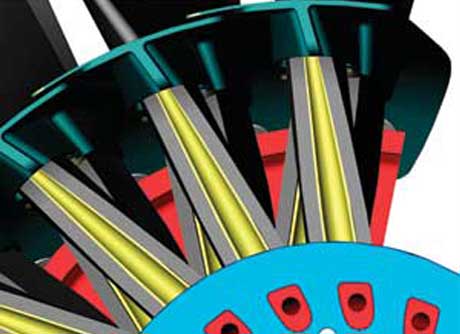
Fan blade leading edge straps attach to the retaining ring (blue).
A new variable pitched turbofan design that could consume as much as 14% less fuel relative to today’s fans is generating excitement in the airline industry, where a few percentage points of increase in fuel efficiency can be the difference between profit and bankruptcy for an airline. Rotating Composite Technologies has come out with a unique patented design and is now working with jet engine companies to develop and test it.
Designing and building machines that can change the orientation of their rapidly rotating parts is a challenge, but the concept of adjusting the pitch angle of tubomachinery blades is key to efficient and successful operation.
Active Pitch Control Common but Not Optimal at All Speeds
An axial flow gas turbine consists of many rows of rotating blades, interspersed with rows of stationary airfoils, called vanes or stators. The hundreds of blades and vanes in a gas turbine are fixed, at pitch angles determined by the designer. Performance could be enhanced by active pitch control, but how does one do this for a rotating machine as complex and as compact as a gas turbine?
A couple of approaches have been tried. General Electric’s variable pitch compressor stator invented in the 1950s changes compressor stator or vane pitch angles by ten to thirty degrees during a flight cycle. These variable stator mechanisms are still used today in most axial flow gas turbines.
Most modern commercial jet engines are turbofans, with a front mounted fan whose size is indicated by the bypass ratio. Designers would like to increase the fan’s bypass ratio to affect the thrust and pressure ratio to reduce fuel consumption, but it is difficult to optimize the fan blade pitch for both low and high flight speeds.
During the 1990’s jet engine companies developed and tested variable pitch turbofans, with cycle studies showing between 6 % and 14% fuel savings. Unfortunately these early designs had variable pitch mechanisms that were too heavy and bulky. They also required hundreds of horsepower to change the fan blade pitches.
Fuel Saving Design Elements
RCT’s variable pitch fan promises to overcome the deficiencies of those tested in the 1990s.
The variable pitch design features a composite fan blade and two flexible carbon fiber composite straps, an integral part for supporting the blades that make it strong enough to safely support the centrifugal load and remain flexible in torsion.
The straps are angled so that the blade centrifugal load is aligned along each strap, thus balancing high centrifugal twisting moments at a neutral position. This greatly reduces the force required to hold or change fan blade pitch.
The two flexible straps allow the blades to be nested close together, so the hub can be sized to current fixed pitch fans. Because the loads are balanced, the force required to change pitch is much less than in previous designs. Thus, the pitch actuator can be smaller and of lighter weight.
A cradle is added to the base of each blade, which provides a center pivot, and also ties each blade torsionally to the pitch change system. The top portion of the cradle forms the flow path between the blades. The lower part protrudes forward, and has a slot that attaches to a timing ring. The pitch change system then rotates this ring, and all blades move synchronously to the desired pitch.
As a safety feature, either of the two straps is capable of supporting the full blade centrifugal load, providing protection from blade loss. If pitch control is lost, the centrifugal twisting forces and the strap torsional/bending forces will balance with the blades moving to a prescribed neutral position, similar to the angle at which fixed pitch fans are built today.
One to Watch
Engine cycle analysis performed with RCT’s design indicates that successful implementation of their variable pitch fan in turbofan engines could result in a 12 to 14 percent reduction in fuel consumption relative to today’s turbofans. Importantly, this result accounts for aircraft installation effects during a typical commercial flight cycle.
If these fuel savings could spread through the airline industry, changing the pitch could lead to air carriers singing a happier tune.
[Adapted from "Fitting a Pitch," by Lee S. Langston, ASME Fellow, for Mechanical Engineering, December 2009.]
Because the loads are balanced, the force required to change pitch is much less than in previous designs. Thus, the pitch actuator can be smaller and of lighter weight.
Fan blade leading edge straps attach to the retaining ring (blue).

Professor emeritus University of Connecticut Dept of Mechanical Engineering
Related Content


