New Guidelines for Pressure Boundary and Bolted Joint Assembly
New Guidelines for Pressure Boundary and Bolted Joint Assembly
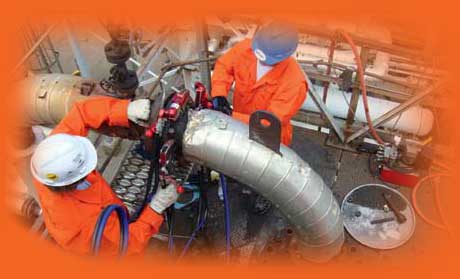
Torquing a flange: Advances in technology, procedures, and calculation methods have been incorporated in the 2010 edition of Guidelines for Pressure Boundary Bolted Joint Assembly.
In 2010, ASME Standards & Certification published a much expanded edition of the standard reference, PCC-1-2010 Guidelines for Pressure Boundary Bolted Joint Assembly replaces the first, 2000 edition. The new publication reflects advances in gasket technology, bolting assembly procedures, and calculation methods.
Safety from Lessons Learned
Since PCC-1’s original release concern arose over incidents of bolted joint leakage, some involving personnel injury, that could have been avoided with relatively minor changes to assembly procedures. PCC-1-2010 incorporates new recommendations based on this experience. For example in section 13.0 “Joint Pressure and Tightness Testing,” a caution was added on the use of temporary gaskets used during pressure and tightness testing. The revision also recommends that gaskets not be reused.
Section 7.0, “Lubrication of Working Surfaces,” was updated to include a recommendation that bolts be checked for free-running nuts during bolt lubrication. This was based on experience indicating that relatively small imperfections on the bolt or nut thread can significantly affect the obtained bolt load when tightening the joint.
Another addition, that excessive paint be removed before assembling the joint, was based on the observation that excessive paint thickness between the nut and back of the flange could cause joint leakage due to loss of the bolt load as the paint degrades.
Previous guidelines for flange face flatness were based on manufacturing tolerances and often did not reflect what practical experience. Nor did they address imperfections in the flange facing. In practice, the acceptable imperfections for a flange facing depend on the type of gasket.
Appendix D, “Guidelines for Allowable Gasket Contact Surface Flatness and Defect Depth,” describe flatness limits based on compression the gasket experiences during assembly. The appendix also covers acceptable levels of local flange facing imperfections, which depend on the materials used.
The revision of Appendix E: “Flange Joint Alignment Guidelines” incorporates a similar departure from older standards. Alignment guidelines for PCC-1-2010 were completely rewritten to focus on geometry-based limits with associated alignment-force limits.
Similarly, Appendix M: “Hardened Washer Usage Guideline and Purchase Specification,” was created to fill a need for a hardened washer specification that suited bolted joint applications for pressure vessels and piping.
Improved Integrity, Less Effort
PCC-1 was updated to improve joint assembly productivity by allowing graphite to remain in the flange surface finish grooves after cleaning when using graphite-faced gaskets. This reduces the effort associated with preparing the joint for reassembly.
Even greater productivity gains are possible through the alternative tightening procedures outlined in Appendix F: “Alternative Flange Bolt Assembly Patterns.”
Since the initial release of PCC-1, considerable effort was made to demonstrate that faster assembly methods can achieve joint integrity equal to or better than those obtainable through older methods. The theory behind these improvements is the use of an appropriate pattern for the gasket being employed and by increasing the bolt load at a much more rapid rate than the legacy method. Pattern passes employing multiple tools have been included to reflect this common industry practice.
Answering Age-Old Questions
Engineers working with pressure vessel and piping bolted joints often face the question of which assembly bolt is more appropriate. Appendix O: “Assembly Bolt Load Selection” outlines two methods of determining the appropriate assembly bolt load for a given joint.
The other significant conundrum involves diagnosing cause(s) of leaks. The new Appendix P: “Guidance on Troubleshooting Flanged Joint Leakage Incidents” covers leakage assessment through examination of the original joint configuration, assembly history, operating conditions, and condition of the joint and gasket subsequent to joint disassembly. The appendix provides guidance, checklists that guide users through joint leakage investigations, and contains a sample “Flanged Joint Leak Report” and additional considerations for common flange design issues and potential resolutions.
Training and Certification
The lack of standardized qualifications for bolted joint assemblers has been identified as an issue by many in industry and is a leading cause of joint leakage due to poor assembly practices.
To improve the status quo, a significant revision to the existing PCC-1 Appendix A was drafted and is under consideration. The proposed new Appendix A outlines requirements for creation and administration of training and assessment programs for certifying bolted joint assemblers, and suggests minimum course content for that certification.
ASME PCC-1-2010 represents a step change in the level of detail provided for guidance on bolted joint assembly and guide continued improvement in the integrity of bolted flanged joints.
[Adapted from “Assembling Knowledge” by Warren Brown, Clyde Neely, and Steven J. Rossi, for Mechanical Engineering, July 2010.]
The lack of standardized qualifications for bolted joint assemblers has been identified as an issue by many in industry and is a leading cause of joint leakage due to poor assembly practices.
Torquing a flange: Advances in technology, procedures, and calculation methods have been incorporated in the 2010 edition of Guidelines for Pressure Boundary Bolted Joint Assembly.
Related Content